Acceleration of Signal Processing functions using Xilinx ZCU111 RFSOC Development Board
Introduction
The Xilinx ZCU111 development board showcases the Xilinx UltraScale+™ RFSOC device. This RFSOC device includes a hardened analog block with multiple 6GHz 14b DAC and 4GHz 12b ADC blocks. Coupled with an ARM A53 processing subsystem, the ZCU111 provides a comprehensive Analog-to-Digital signal chain for application prototyping and development. This document demonstrates how users can develop accelerated signal processing applications using the Xilinx Vitis IDE software and a modified ZCU111 platform. User-defined accelerated kernels are integrated into the platform via the Vitis tool. This project creates a free-running kernel that can process waveform data loaded into UltraRAM via linux script. The kernel output interfaces to a half-band filter with its output driving the DAC interface of the RFDC block. The DAC output is looped back to the ADC and captured in local BRAM. Matlab scripts are provided to create the input waveforms as well as process the resultant ADC waveform for comparison. Linux scripts are also available to modify the platform clocking rates to create higher sampling rates for higher data rate applications.
Base Platform Details
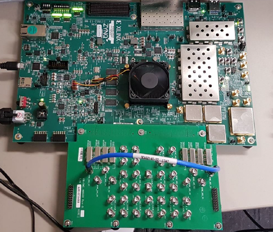
A Vitis software platform is a combination of both a Programmable Logic design coupled with a PS based software application. This application starts with a base platform with the following features. A single DAC channel is looped back to a single ADC channel. The sampling rate for both the DAC and ADC is set to 1.47454Ghz. The PL design plays a 32K continuous waveform programmed into UltraRAM to DAC ch7. The waveform is created via Matlab script. The DAC output is looped back to ADC ch0 and a 4K sample is captured using BRAM. The DAC output (DAC229 Ch3) is connected via dc-1330Mhz low pass filter to ADC224 Ch0. See board image below
Base Platform Clocking
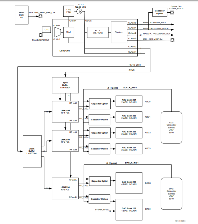
The platform is setup for DAC and ADC sampling rates of 1.47454 GHz. If another sampling frequency is desired the linux script can be modified. This may also require a modification to the hardware platform and the RF data converter IP using Vivado IPI.
The ZCU111 ADC/DAC clocks are generated from the LMK04208 feeding 3 LMX2594 in parallel. For more information on clocking review the RF Data Converter Clocking section in the ZCU111 board user guide UG1271 . Clocking is configured via a I2C to SPI bridge. See diagram below. Programming of the clocks is performed via script included in the Linux build.
Creating the Acceleration Platform
Hardware Modifications
The base platform is modified to enable the insertion of an accelerated function via the Xilinx® Vitis™ unified software platform IDE. The accelerated function will read the waveform from UltraRAM memory, process the data and write it to a half band 2x interpolating filter (part of the base platform). The output of the filter is written into the RFDC DAC interface via AXI streaming interface. The RFSOC DAC interface captures 8 samples per AXI clock running at 184.32 Mhz. A block diagram is shown below
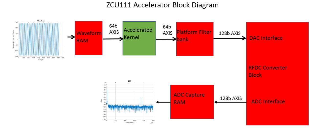
To enable the addition of an accelerator function, some modifications need to be made to the base IPI (IP Integrator) block diagram to create a custom platform for acceleration. The UltraRAM axis output and the FIR filter axis input are left unconnected and PFM(Platform) properties are applied to these ports to identify them as possible connection points for the accelerated function. The clock used by the accelerator also needs to have a PFM (platform) property defined. The PFM properties are defined using the Platform Interface window with IPI. In this window, you enable the connections and define them by sptag name. Vitis technology connects the dac_path kernel into the platform during the build process based on the stream connect definitions using the sptag name in the connectivity file. The connectivity file is shown below

After the PMF property modifications are made to the base platform the design needs to be resynthesized and Implemented. Following successful implementation, a bitstream is created. The XSA can now be created.
XSA (Xilinx Support Archive) Creation
For embedded platform creation in the Vitis tool, additional properties need to be set to define platform intent. They are shown below. The default output type is going to be associated with what you want to create. For typically embedded platforms, sd card and/or qspi are typical options. The required platform intent properties are shown below
    set_property platform.design_intent.embedded true [current_project]
set_property platform.design_intent.server_managed false [current_project]
set_property platform.design_intent.external_host false [current_project]
set_property platform.design_intent.datacenter false [current_project]
set_property platform.default_output_type "hw_export|qspi|sd_card|xclbin" [current_project]
After setting the properties above you then need to create and validate the XSA. The tcl commands to do so are below.
    write_hw_platform -include_bit -force name.xsa

validate_hw_platform name.xsa.
Building the XRT stack and Custom Applications with Yocto
Vitus is a powerful tool to help developers accelerate their applications on Xilinx SoC and ACAP class devices. Here we will focus on building the XRT stack and applications to support a loopback RF design that will play and capture a waveform using the ZCU111 evaluation board.
We will create two Yocto layers, one for the XRT stack and one for the user’s applications. To start, you will need to clone the Xilinx Yocto repositories. The recommended flow is to use repo to manage the various Yocto and Xilinx git repositories (How to build images through yocto). Once you have these installed, you can begin to add the XRT and application layers.
Create the XRT layer
Once Xilinx Yocto is installed, source “setupsdk” from the Yocto root directory and then “cd” into the “sources” directory
    $ source setupsdk

$ cd ../sources

$ bitbake-layers create-layer meta-xrt
NOTE: Starting bitbake server...
Add your new layer with 'bitbake-layers add-layer meta-xrt'
Note, we will add “meta-xrt” to “bblayers.conf” later. Inside the “meta-xrt”, clone the XRT repo.
    $ cd meta-xrt

$ git clone https://github.com/Xilinx/XRT.git
The XRT repo contains a set of recipes required to support the XRT stack. You can manually copy these recipes into your layer from the repo, but we will change the search path so we don’t need the extra copy. This also make it easier to update the repo and keep the recipes in sync. Edit the “conf/layer.conf” file in your layer as shown below.
# We have recipes-* directories, add to BBFILES
BBFILES += "${LAYERDIR}/recipes-*/*/*.bb \

            ${LAYERDIR}/recipes-*/*/*.bbappend \

            ${LAYERDIR}/XRT/src/platform/recipes-*/*/*.bb \

            ${LAYERDIR}/XRT/src/platform/recipes-*/*/*.bbappend"
Now when you update the XRT repo with “git pull”, you don’t need to manually copy the recipes. Next let’s create some other recipe directories to support XRT
    $ mkdir -p recipes-bsp/{bootbin, device-tree/files}

$ mkdir -p recipes-core/images

$ mkdir -p recipes-xrt/xrt/files
Inside the “recipes-xrt/xrt” directory, create “xrt_%.bbappend” as shown below to install our XRT init script
    FILESEXTRAPATHS_prepend := "${THISDIR}/files:"

SRC_URI += " \

       file://xrt.sh \

"

do_install_append () {

       install -d ${D}${sysconfdir}/profile.d

       install -m 0755 ${WORKDIR}/xrt.sh \

             ${D}${sysconfdir}/profile.d/xrt.sh

}

FILES_${PN} += "${sysconfdir}/*"
Next create the init script “xrt.sh” in the “files” directory as shown below. This will set the environment variable XILINX_XRT at boot.
Next let’s add the XRT packages to the final image. Create “petalinux-image-minimal.bbappend” in “recipes-core/images” as shown below.
Now we will add some BSP support for XRT. In the “recipes-bsp/device-tree”, let’s create the “devicetree.bbappend" as shown.
    IMAGE_INSTALL_append = " \

xrt \

xrt-dev \

zocl \

       ocl-icd \

opencl-headers \

opencl-clhpp \

"

FILESEXTRAPATHS_prepend := "${THISDIR}/files:"

MYAPP_DTSI = "myapp.dtsi"

SRC_URI_append = " \

       file://${MYAPP_DTSI} \

"

do_configure_append() {

       cp ${WORKDIR}/${MYAPP_DTSI} ${B}/device-tree

       echo '/include/ "${MYAPP_DTSI}"' >> \

${B}/device-tree/system-top.dts
Inside the “files” directory add the “myapp.dtsi” include file as shown below. This node will bind the driver in the kernel when the kernel boots. We will also disable the AXI GPIO driver binding since the zcu111 RFDC clocks may not be up when Linux boots. For simplicity we will write directly to the AXI GPIO registers with devmem, but you could also bind the driver once the clocks are enabled through a device tree overlay or by loading the AXI GPIO driver as a module and use sysfs to control the GPIO.
    &amba {

       zyxclmm_drm {

             compatible = "xlnx,zocl";

             status = "okay";

       };

};

&axi_gpio_0 {

   status = "disabled";

};

&axi_gpio_dac {

   status = "disabled";

};
The last thing we are going to do in the XRT layer is optional, but it may help when creating a platform in Vitus. In the “bootbin” directory create “xilinx-bootbin_%.bbappend” and edit it as shown below. This will deploy the Bootgen BIF file which we can later use to support our platform in Vitus
    do_deploy_append () {

       install -m 0444 ${BIF_FILE_PATH} ${DEPLOYDIR}/boot.bif

       ln -sf boot.bif ${DEPLOYDIR}/boot-${MACHINE}.bif

}
Create the Application layer
Now let’s create the application layer. In this example I’ve named it “myapp”, but you may name it anything that better describes your application.
    $ cd <path-to>/sources

$ bitbake-layers create-layer meta-myapp
NOTE: Starting bitbake server...
Add your new layer with 'bitbake-layers add-layer meta-myapp'
require conf/machine/zcu111-zynqmp.conf
Next let's create the directories to support a custom machine configuration and init scripts.
    $ mkdir -p conf/machine

$ mkdir -p recipes-core/initscripts/files
Create a machine configuration in “conf/machine”. For this example, we will call it myapp-zcu111-zynqmp.conf where the tuple indicates the name of our project, the board and the architecture. The machine configuration starts by requiring the “zcu111-zynqmp.conf” so that we can inherit all the properties of the zcu111 machine. Once we do that, we can make modification as needed. Here we can add our “xsa” file exported from Vivado. We add the dtb that is generated from the DTG and include the boot.scr to customize the u-boot environment. We also install packages specific to our machine including the initialization scripts and RFDC and associated examples.
    HDF_EXT = "xsa"

HDF_BASE = "file://"

HDF_PATH = "<path-to>/<name-of>.xsa"

YAML_DT_BOARD_FLAGS = "{BOARD zcu111-reva}"

EXTRA_IMAGEDEPENDS_append = " u-boot-zynq-scr"

DEVICE_TREE_NAME = "${MACHINE}-system.dtb"

IMAGE_INSTALL_append = " \

       rfdc \

       rfdc-dev \

       rfdc-read-write \

       rfdc-selftest \

"

IMAGE_INSTALL_append = " \

sysvinit-myapp \

sysvinit-myapp-waveform \

"
Now we can create the application recipe for the initialization scripts in the “recipes-core/initscripts” directory. This is straight forward as we are installing two scripts, one for configuring the clocks and one for loading the waveform. Each script has an associated conf file for user configuration as well as one or more firmware files. Note, you need to replace “rfsoc_1p47456_100m_65536_-5db_8_23.bin” with your waveform file.
SUMMARY = "ZCU111 sysvinit scripts"

SECTION = "ZCU111/init"

LICENSE = "MIT"

LIC_FILES_CHKSUM = "file://${COMMON_LICENSE_DIR}/MIT;md5=0835ade698e0bcf8506ecda2f7b4f302"

RDEPENDS_${PN} = "bash"

COMPATIBLE_MACHINE = "^$"

COMPATIBLE_MACHINE_zynqmpdr = "zynqmpdr"

PACKAGE_ARCH = "${MACHINE_ARCH}"

SRC_URI = " \

file://zcu111-clocks \

file://zcu111-clocks.conf \

file://zcu111-wavetable \

file://zcu111-wavetable.conf \

file://lmk04208.122880.fw \

file://lmx2594.1474560.fw \

file://rfsoc_1p47456_100m_65536_-5db_8_23.bin \

"

S = "${WORKDIR}"

do_configure[noexec] = "1"

do_compile[noexec] = "1"

inherit update-rc.d

INITSCRIPT_PACKAGES = "${PN} ${PN}-wavetable"

INITSCRIPT_NAME = "zcu111-clocks"

INITSCRIPT_PARAMS = "start 80 S ."

INITSCRIPT_NAME_${PN}-wavetable = "zcu111-wavetable"

INITSCRIPT_PARAMS_${PN}-wavetable = "start 81 S ."

do_install() {

install -d ${D}${sysconfdir}/init.d

install -d ${D}${sysconfdir}/zcu111

install -m 0755 ${S}/zcu111-clocks \ ${D}${sysconfdir}/init.d/zcu111-clocks

install -m 0755 ${S}/zcu111-clocks.conf \ ${D}${sysconfdir}/zcu111/zcu111-clocks.conf

install -m 0755 ${S}/zcu111-wavetable \ ${D}${sysconfdir}/init.d/zcu111-wavetable

install -m 0755 ${S}/zcu111-wavetable.conf \ ${D}${sysconfdir}/zcu111/zcu111-wavetable.conf

install -m 0644 ${S}/lmk04208.122880.fw \ ${D}${sysconfdir}/zcu111/lmk04208.122880.fw

install -m 0644 ${S}/lmx2594.1474560.fw \ ${D}${sysconfdir}/zcu111/lmx2594.1474560.fw

install -m 0644 ${S}/rfsoc_1p47456_100m_65536_-5db_8_23.bin \ ${D}${sysconfdir}/zcu111/rfsoc_1p47456_100m_65536_-5db_8_23.bin

}

PACKAGES =+ "${PN}-wavetable"

FILES_${PN} = " \

   ${sysconfdir}/init.d/zcu111-clocks \

   ${sysconfdir}/zcu111/zcu111-clocks.conf \

   ${sysconfdir}/zcu111/lmk04208.122880.fw \

   ${sysconfdir}/zcu111/lmx2594.1474560.fw \

FILES_${PN}-wavetable = " \

   ${sysconfdir}/init.d/zcu111-wavetable \

   ${sysconfdir}/zcu111/zcu111-wavetable.conf \

   ${sysconfdir}/zcu111/rfsoc_1p47456_100m_65536_-5db_8_23.bin \

"
"Next, we will configure the four clocks on the ZCU111 with the “zcu111-clocks” script. There are no Linux drivers for these devices in the kernel, so we will script it because it’s easier to maintain and can be modified at runtime. As the developer, you could also choose to write an application that does this instead of using the script. The zcu111-clocks.conf config file will define the default state of the clocks at boot as shown below. The “*_FW” vaiables essentially point to the firmware files that are written to each clock device. The script expects “<device>.<frequencyKHz>” format. The actual files will have a “fw” extension to indicate these are firmware files. See Appendix A for clock firmware.
# zcu111-clocks.conf

# SPICLK 00:1842kHz, 02:115kHz

SC18IS602_SPICLK=0x02

LMK04208_FW=lmk04208.122880

LMX2954A_FW=lmx2594.1474560

LMX2954B_FW=lmx2594.1474560

LMX2954C_FW=lmx2594.1474560

#!/bin/sh

# zcu111-clocks

ZCU111_CONFDIR=/etc/zcu111

SC18IS602_ADDR=0x2F

LMK04208_ADDR=0x02

LMX2954A_ADDR=0x08

LMX2954B_ADDR=0x04

LMX2954C_ADDR=0x01

SC18IS602_config ()

{

echo -n "Configuring SC18IS602..."

i2cset -y $SC18IS602_BUS $SC18IS602_ADDR 0xF0 $1

is_err $?

echo "Done"

}

LMK04208_config ()

{

FILE="$2.fw"

echo -n "Configuring $2..."

while read -r b0 b1 b2 b3

do

if [[ ${b0:0:1} != '#' ]]; then

i2cset -y $SC18IS602_BUS $SC18IS602_ADDR $1 \

0x$b0 0x$b1 0x$b2 0x$b3 i

is_err $?

fi

done < "$ZCU111_CONFDIR/$FILE"

echo "Done"

}

SC18IS602_BUS=$(grep -rs sc18is603 /sys/bus/i2c/devices/*/name \

| sed 's/\/sys\/bus\/i2c\/devices\///;s/-.*//')

if [ -z "$SC18IS602_BUS" ]; then

echo "ERROR: Can't find an i2c bus hosting SC18IS602"

exit 1

fi

case "$1" in

start)

SC18IS602_config $SC18IS602_SPICLK

LMK04208_config $LMK04208_ADDR $LMK04208_FW

LMX2594_config $LMX2954A_ADDR $LMX2954A_FW

LMX2594_config $LMX2954B_ADDR $LMX2954B_FW

LMX2594_config $LMX2954C_ADDR $LMX2954C_FW

;;

reload)

       echo “reload clocks here”

       ;;

*)

echo $"Usage: $prog {start|reload}"

exit 1

esac
Now we will add a script to fill the BRAM with the waveform. We will use a binary file created in Matlab. The format of the Matlab data file is expected to be 16-bit samples in little endian format. The first file is a conf file that will be sourced in by the script. This will define the address and size of the BRAM for the wavetable, the address of the AXI GPIO controller which controls playback and the binary file containing the waveform. We will pack the 16b samples into 32b words to make the writes more efficient.
# zcu111-wavetable.conf

WAVETABLE_ADDR=0xA0060000

WAVETABLE_SIZE_K=64

WAVETABLE_CTRL=0xA0041000

WAVETABLE_FILE=rfsoc_1p47456_100m_65536_-5db_8_23.bin

#!/bin/sh

# zcu111-wavetable

ZCU111_CONFDIR=/etc/zcu111

load_wavetable ()

{

PACK=0; OFF=0; BPERWD=4; SIZE=$(($WAVETABLE_SIZE_K * 1024))

echo -n "Loading ${WAVETABLE_SIZE_K}KB wavetable: $WAVE..."

cat $WAVE | hexdump -v -e '/2 "%04X\n"' | \

while read -r SAMPLE

do

if [ $PACK -eq 0 ]; then

LOW=$SAMPLE

PACK=1

else

devmem $(($WAVETABLE_ADDR + $OFF)) 32 0x$SAMPLE$LOW

is_err $?

((OFF += $BPERWD))

if [ $OFF -eq $SIZE ]; then

       break

fi

PACK=0

fi

done

echo "Done"

}

enable_player ()

{

echo -n "Player: "

devmem $WAVETABLE_CTRL 32 0x1

is_err $?

echo "Enabled"

}

disable_player ()

{

echo -n "Player: "

devmem $WAVETABLE_CTRL 32 0x0

is_err $?

echo "Disabled"

}

trigger_player ()

{

echo -n "Player: "

devmem $WAVETABLE_CTRL 32 0x3

sleep .1

devmem $WAVETABLE_CTRL 32 0x1

echo "Triggered"

}

is_err ()

{

if [ $1 -gt 0 ]; then

echo "ERROR"

exit 1

fi

}

if [ -f $ZCU111_CONFDIR/zcu111-wavetable.conf ]; then

. $ZCU111_CONFDIR/zcu111-wavetable.conf

else

echo "ERROR: zcu111-wavetable.conf not found"

exit 1

fi

if [ -f $ZCU111_CONFDIR/$WAVETABLE_FILE ]; then

        WAVE=$ZCU111_CONFDIR/$WAVETABLE_FILE

else

        echo "ERROR: $ZCU111_CONFDIR/$WAVETABLE_FILE file not found"

        exit 1

fi

case "$1" in

start)

load_wavetable

enable_player

trigger_player

;;

stop)

disable_player

;;

reload)

WAVE=$2

if [ ! -f $WAVE ]; then

echo "ERROR: $WAVE file not found"

exit 1

fi

disable_player

sleep 1

load_wavetable

enable_player

trigger_player

;;*)

echo $"Usage: $prog {start|stop|reload <file>}"

exit 1

esac
This script also allows you to reload the wavetable with a new waveform from the Linux command line at runtime.
$ /etc/init.d/wavetable reload <new-waveform>.bin
At last we will hook the layers into the Yocto build. Edit “build/conf/bblayers.conf” and add the “meta-xrt” and “meta-myapp” layers we just created. This could be automated with the “bitbake-layers add-layer” Yocto script, but I find simply editing “bblayers.conf” to be quicker and easier.
    BBLAYERS ?= " \

.

.

/<path-to>/meta-xrt \

/<path-to>/meta-myapp \

"
Build Your Images
$ MACHINE=myapp-zcu111-zynqmp bitbake petalinux-image-minimal
After building, your images are located in the “build/tmp/deploy/images/myapp-zcu111-zynqmp” directory. Vitus will need the boot ELF images (fsbl, pmufw, bl31, u-boot) and a BIF to generate a BOOT.bin. Note, you will need to edit the BIF file to replace the hard ELF paths with the tokens that the Vitis tool expects using the format <image.elf>. Your BIF should look something like the listing below.
    the_ROM_image:

{

[bootloader, destination_cpu=a53-0] <fsbl.elf>

[pmufw_image] <pmufw.elf>

[destination_device=pl] <bitstream>

[destination_cpu=a53-0, exception_level=el-3, trustzone] <bl31.elf>

[destination_cpu=a53-0, exception_level=el-2] <u-boot.elf>

}
Build the SDK
$ MACHINE=myapp-zcu111-zynqmp bitbake petalinux-image-minimal -c populate_sdk
The SDK is required by Vitus to provide the sysroot for building Linux applications. Once this is built, just execute the shell script (.sh) deployed in “build/tmp/deploy/images/myapp-zcu111-zynqmp” and install into a directory of your choice.
Vitis IDE Platform Creation
Using the XSA created from Vivado earlier and the files from the Yocto build we can use the Vitis IDE to create our custom platform. First launch the Vitis tool and select Vitis Create Platform Project The images below show the steps required to create the custom platform.
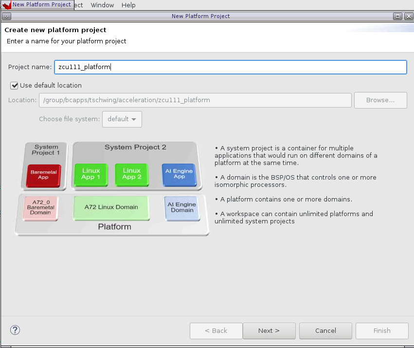
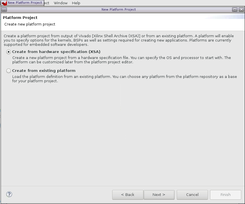
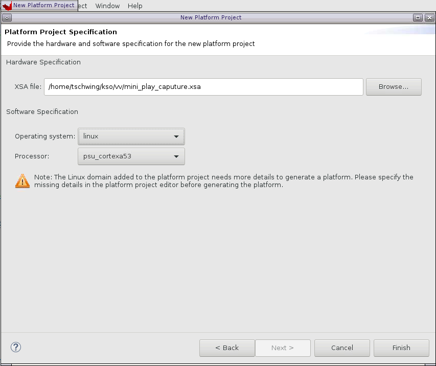
Select the linux on psuA53 domain and set the paths for the boot directory, bif file, image and sysroot directories created from the linux kernel creation defined above. See diagram below.

Vitis Acceleration Project Creation
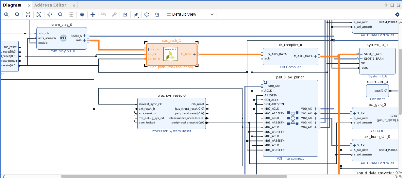
Once the platform is successfully created in the Vitis tool, it can be used to create an acceleration project targeting the custom platform. The project includes both host code and user kernel code. For typical accelerated projects the host code will include the traditional OPEN CL API calls to identify the available platforms and devices available, create the required context, identify the accelerated kernels, and enqueue their execution. The kernel code can be created using OPEN CL, C/C++ or RTL code. For this application, the kernel will be created as a free running kernel. This means once the kernel is loaded into the platform the host code will release it and it runs continuously without further host code intervention. This is expected since the platform has the accelerator function connected between to PL blocks. Since the waveform is played continuously from UltraRAM the accelerated kernel also needs to run continuously without host code interruptions. Below is a Vivado IPI diagram after a successful project build. It shows our kernel connects to the URAM and filter platform blocks. The HLS symbol on the block indicates the kernel was synthesized via Vivado HLS tool.
Testing the Application
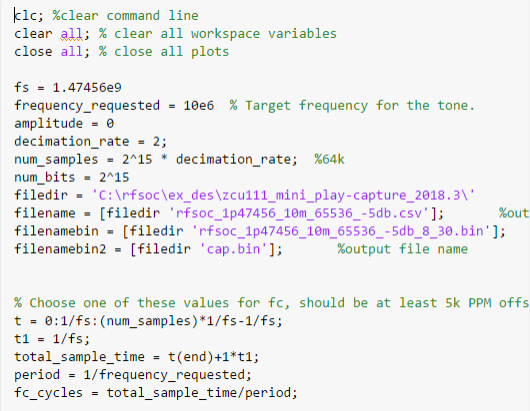
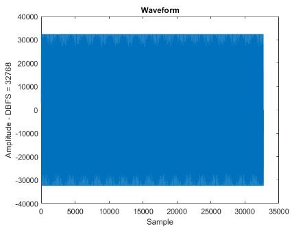
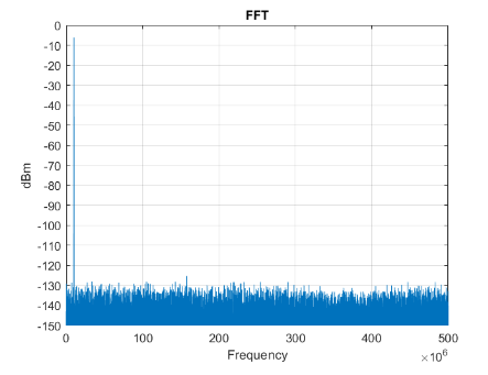
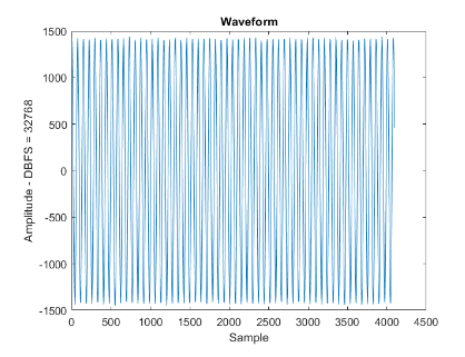
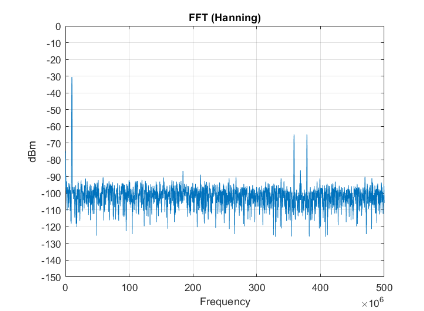
Matlab scripts are provided to create the waveform written into the UltraRAM and also to analyze the captured ADC output file. The waveform creation script will display a graph of the created waveform and plot an FFT of the waveform. Snipits of these matlab scripts are shown below
Waveform generation
ADC Capture Matlab Script
    clc; %clear command line
clear all; % clear all workspace variables
close all; % close all plots

% Base directory for all source and output files
filedir = 'C:\rfsoc\ex_des\zcu111_mini_play-capture_2018.3\'
%decimation rate
decimation_rate = 1;
decimation_rate2 = 2;
% bin file used for a FFT capture.  Can be either input or output.
filenamebin2 = [filedir 'cap.bin']
%filenamebin2 = [filedir 'mem.bin']
%filenamebin2 = [filedir 'rfsoc_1p47456_10m_65536_-5db_test.bin']

% files for MTS ADC captures
filebinsync0 = [filedir 'cap.bin']
%filebinsync0 = [filedir 'rfsoc_1p47456_10m_65536_-5db.bin']

fidadc0=fopen(filebinsync0,'r');
%Yadc0c = fread(fidadc0,32768,'int16',0,'native');
Yadc0c = fread(fidadc0,4096,'int16',0,'native');
fclose(fidadc0);

fs = 1.47456e9
%fc = 100e6
%amplitude = -10
num_samples = 4096  %128k
%num_samples = 32768
%num_bits = 2^15
num_bits = 2^12

fid3=fopen(filenamebin2,'r');
Y3 = fread(fid3,num_samples,'int16',0,'native');
Y3t = transpose(Y3)

Y3tdb =(Y3t*1/num_bits)
fclose(fid3);
fs = fs/2;
t = 0:1/fs:(num_samples)*1/fs-1/fs;
Conclusion
The RFSOC ZCU111 is a powerful platform for developing traditional signal processing applications. Traditional RTL development is a lengthy process and changes require re-validation through traditional RTL simulation processes. Using Vitis technology, users can create optimized kernels using C/C++, OPEN CL, or RTL that can be used with the provided acceleration platform to quickly create high performance comms applications.


About Tom Schwing
Tom Schwing has been a Field Application Engineer for AMD for 19 years. He has recently moved into an SFAE role concentrating on application acceleration. Prior to this, he was the AMD dedicated FAE for Avnet Distributors. Tom also worked on the Vertical Launch System for Lockheed Martin, various transponder projects for Allied Signal/Raytheon, and the navigation equipment for the Trident submarine with Sperry. He has a BSEE from the University of Scranton and a MSEE from Johns Hopkins University. He is married with two daughters. Tom enjoys playing golf and attending Dave Matthews Band concerts with his family every year.

About Emil Lenchak
Emil Lenchak is a Processor Specialist at AMD in the Southeast region in North America. He specializes in ARM-based SoC and ACAP processors as well as MicroBlaze soft-cores. Emil also has a software focus with expertise in embedded Linux, Yocto, virtualization, and containers. Prior to joining AMD, Emil has supported a variety of customers on microcontrollers, DSP processors and digital satellite radio baseband ASICs. He holds a BSEE from Penn State University.

About John Arens
John Arens is a DSP Specialist FAE at AMD. He helps customers design with AMD DSP IP, and DSP enhanced silicon products like the RFSoC and Versal product lines. John has extensive DSP and Python experience and enjoys when the two come together to form interesting product demos. In his spare time, he spends his time with family, hiking, and traveling.